PCB gallery 1
This time I wanted to post some photos of old PCBs I've designed in the last couple of years. All these boards are related to my Game Boy research activities, which started back in 2014. I was building a Game Boy emulator (Mooneye GB) and found existing documentation about the system lacking in detail, so I started doing my own research. In order to find information about the system, I started studying the hardware with the help of custom circuit boards. I had very little experience with electronics, having barely passed the basic electronics course at the university after multiple attempts, but I started from very simple designs so deep knowledge was not required at first.
My initial choice of PCB design software was CadSoft Eagle, which had a free version with some limitations that didn't affect my designs at first. However, At some point I was starting to hit both size and layer limitations of Eagle, and had to choose between paying for Eagle or switch to some alternative. I don't remember exactly what the pricing model of Eagle looked like, but having support for a smallish 4-layer design was way too expensive, so I started slowly switching to KiCad. This process took a fairly long time, because the workflow was quite different and KiCad had (and still has) some very rough edges. However, I can now say the transition was 100% worth it, and I'm very happy with KiCad.
Almost all of the following PCBs were manufactured by Elecrow, who I used for a long time as the primary manufacturer for all my designs. I was and still am very happy with them, but unfortunately my current designs often require more advanced manufacturing capabilities (e.g. minimum track size) than what is supported by Elecrow, so I haven't used their services recently.
GB-BRK-M v2.1
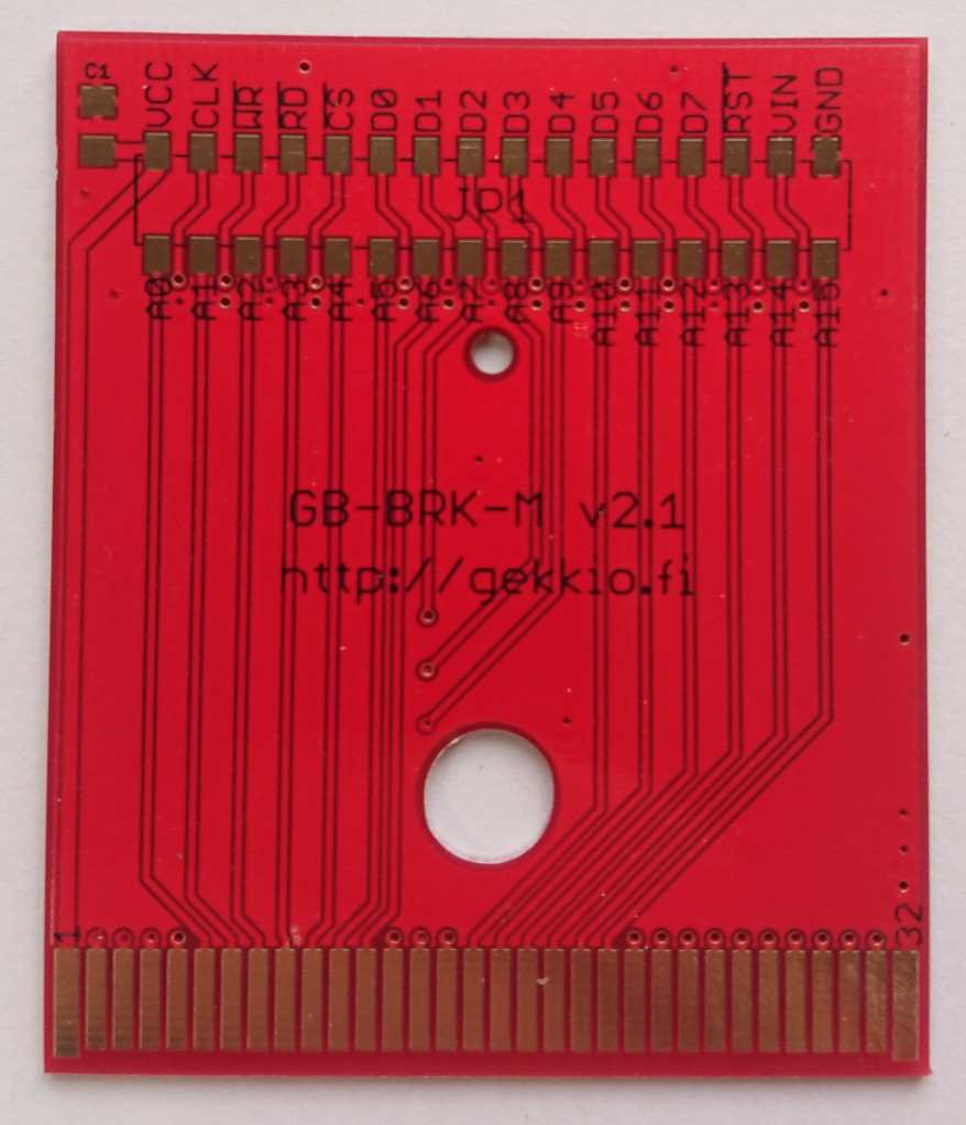
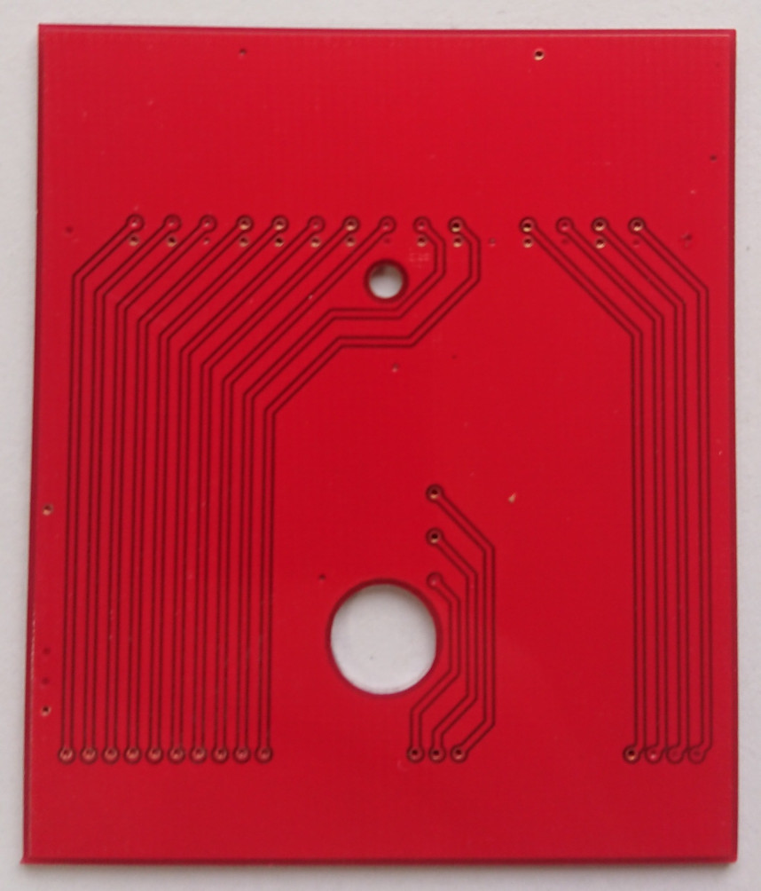
Designed with Eagle, manufactured in 2016 by Elecrow.
This board was an updated version of GB-BRK-M, the breakout cartridge that started my PCB design journey in 2014. The basic idea is to have a Game Boy cartridge that has no other functionality than just giving me access to all the signals. This could then be connected to some actual circuitry in a breadboard or other PCBs. The original v1.0 version had just a PTH pin header and the NPTH holes used by official cartridge shells. It turns out using a PTH part is a bad idea because the pins stick out from the bottom so the PCB won't fit nicely in a cartridge shell. I also screwed up the NPTH hole sizes and placements, so the v1.0 board was quickly followed up by GB-BRK-M v2.0, which switched the pin header to SMT and had correct NPTH holes. Or at least that's what I thought...turns out I screwed up the NPTH holes again, so they were fixed in v2.1, which is the version you can see in the photos.
This v2.1 board also has an interesting manufacturing flaw: I chose white silkscreen (I've double-checked the order confirmation e-mail), but Elecrow made a mistake and gave me black silkscreen. Black text on red background has poor contrast, but this is a fairly harmless mistake, so I didn't even complain about it. 😊
GB-BRK-M v3.0

Designed with KiCad, manufactured in 2017 by Elecrow.
One of the first things I did when learning KiCad was a redesign of the GB-BRK-M board with it. This time I also added LEDs for control signals, so the board is quite a lot more complicated than the original Eagle one.
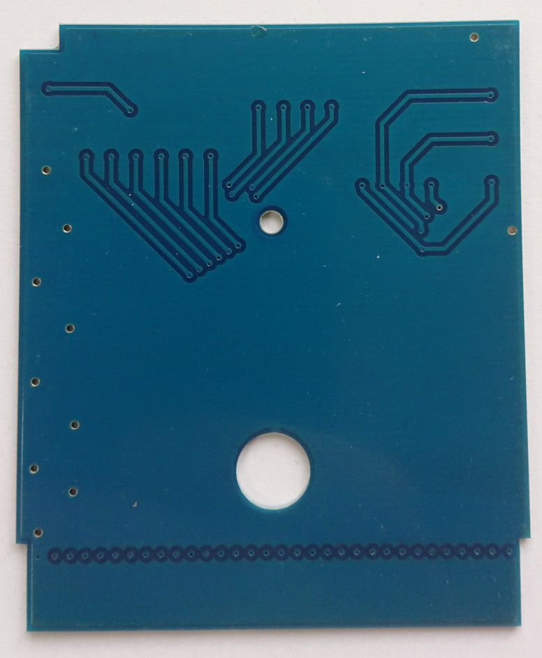
GB-BRK-CART v4.0
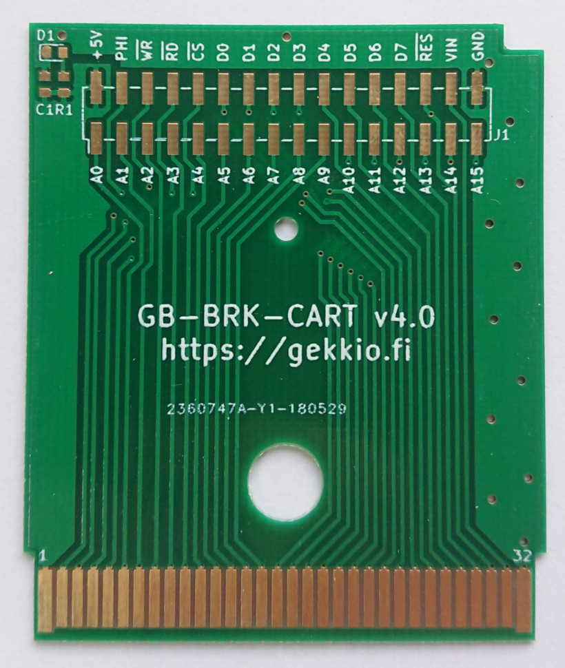
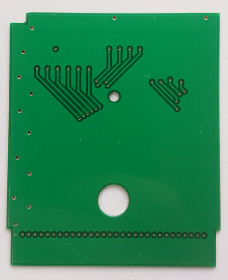
Designed with KiCad, manufactured in 2018 by JLCPCB.
After designing GB-BRK-M, I started having second thoughts about the control LEDs, because I wanted to keep the board as simple as possible and avoid affecting the signals too much with extra circuitry. I also decided to rename the board to GB-BRK-CART to emphasize that this is a cartridge, instead of using "male/female" terminology which is not so obvious.
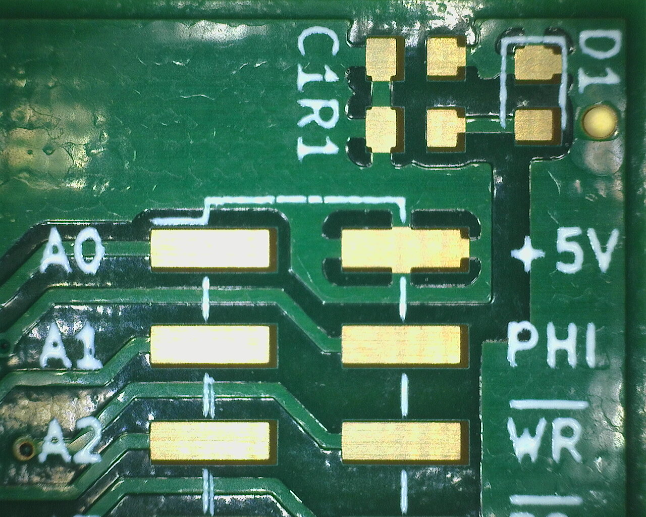
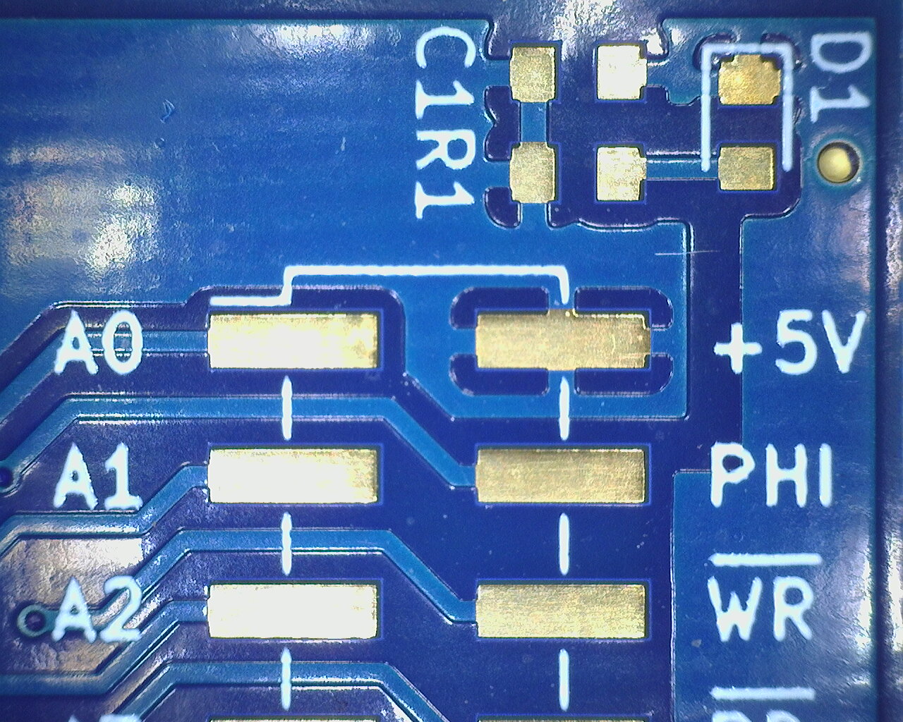
The green board in the photo above came from JLCPCB, who I tried out of curiosity at this point. In order to compare manufacturers, I also got some blue boards from Elecrow using the exactly same Gerber files. The results were interesting, because after hearing many good comments about JLCPCB, the board was inferior to the Elecrow board.
In these microscope photos, you can clearly see how the JLCPCB board (green) has lower silkscreen quality and soldermask accuracy compared to the Elecrow board (blue).
After doing this comparison, I didn't feel very impressed by JLCPCB, so I continued using Elecrow. However, as time passed, my designs started getting more complicated so eventually I had to stop using Elecrow and make the switch.
GB-BRK-F v1.0
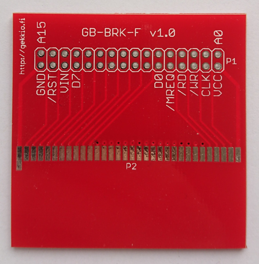

Designed with Eagle, manufactured in 2016 by Elecrow.
This board is the counterpart to GB-BRK-M and allows access to cartridge slot signals using a double-row pin header. The cartridge slot footprint was designed for DX 37787 replacement part (no longer available), but I forgot about the mounting pins on it so it never fit very well on this board. Oops!
GB-BRK-F v2.0


Designed with Eagle, manufactured in 2016 by Elecrow.
After doing GB-BRK-F, I realized it would be useful to have two pin headers for easy bypass functionality while still having access to the signals, so I designed v2.0. The slot footprint is still poor in this one...
GB-INV-DMG v1.0
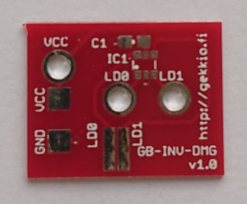
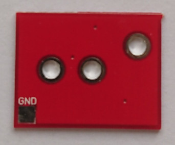
Designed with Eagle, manufactured in 2016 by Elecrow.
This board was one of my many experimental designs of a simple dual inverter board used for DMG biverting.
PICDEV-18F45K50 v1.0

Designed with Eagle, manufactured in 2016 by Elecrow.
This board was an experiment to see if I could design a very simple development board for the PIC18F45K50 MCU, which is one of the cheapest MCUs with built-in USB support. It worked, but there were several flaws:
- it uses MAX603/604 LDO, which is overkill for this and fairly expensive
- it uses a USB Micro connector which is worse than USB Mini. At the time I also didn't have a hot air station so soldering this connector was pretty much impossible. I got it to work, but the soldering quality was awful.
Even with these flaws it was a good experiment, and I still sometimes use PIC18(L)F45K50 for applications where USB support is needed.
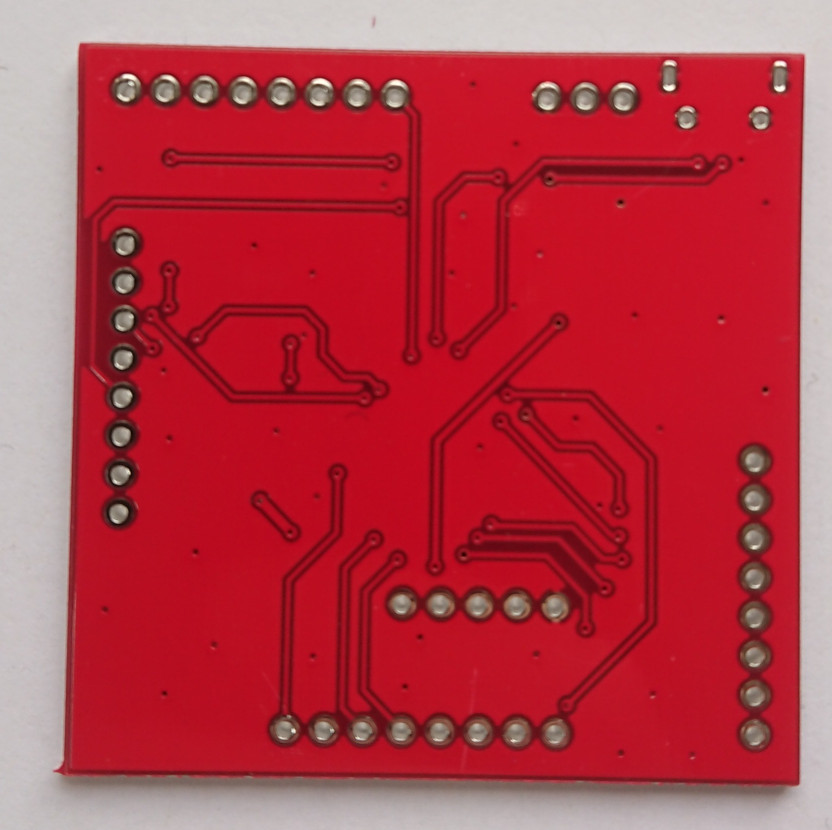
GB-LIVE32 v1.1

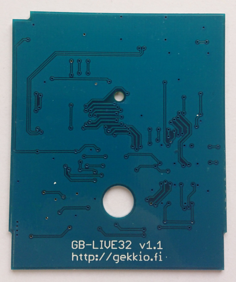
Designed with Eagle, manufactured in 2016 by Elecrow.
This is the second version of GB-LIVE32, a rapid development cartridge for Game Boy. Basically it's a Game Boy cartridge backed by a 32 kB SRAM, which is seen as the "cartridge ROM" by the Game Boy.
I made the terrible mistake of using HASL as the surface finish. This is a bad idea for Game Boy cartridges, because HASL is not really suitable for PCB edge connections. All of the boards started having reliability issues after maybe 20 insertions, so I learned from this mistake and have since then always remembered to use ENIG.
GB-BENCH v1.0
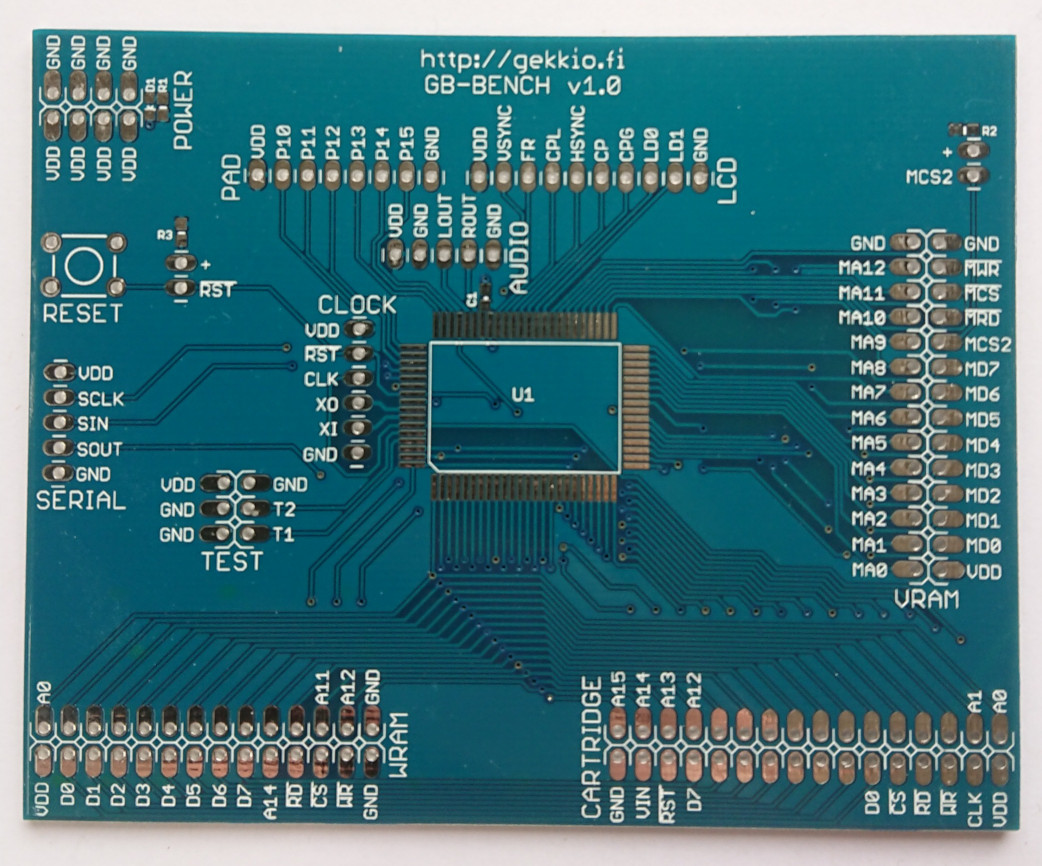
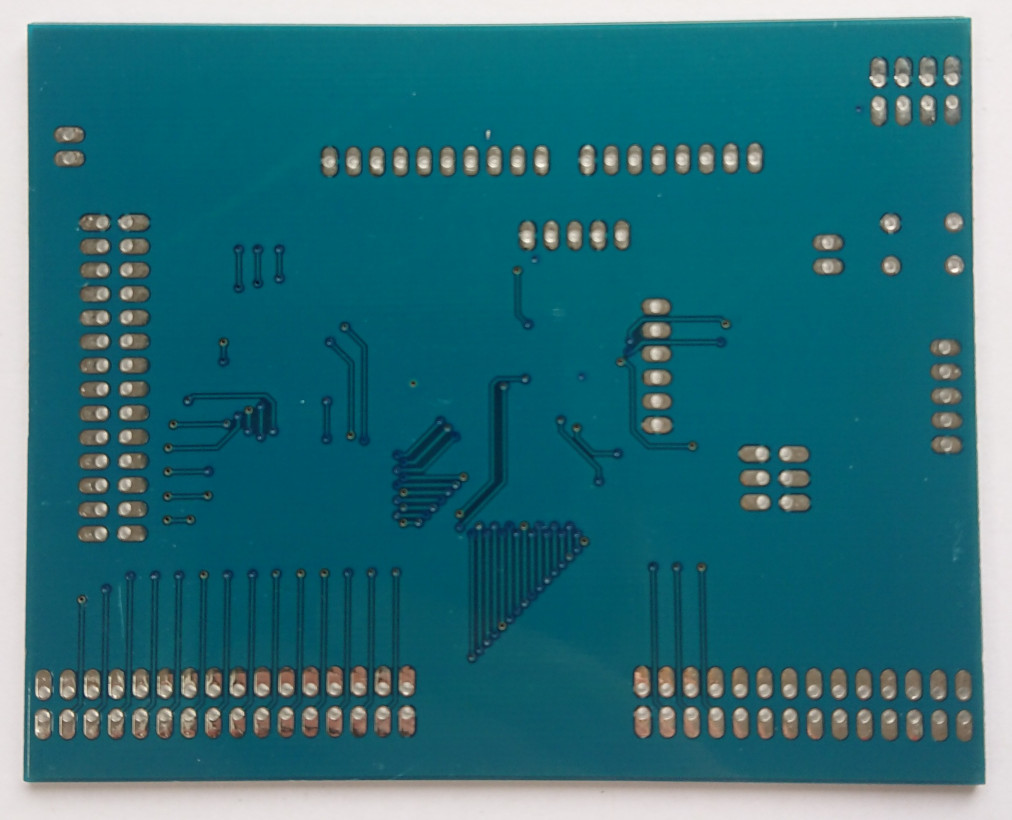
Designed with Eagle, manufactured in 2016 by Elecrow.
This is the first Game Boy test bench board I designed. The basic idea is to desolder a Game Boy CPU chip from a real unit, and put it on a board with the necessary basic circuitry to make it work. Pin headers provide access to all signals, and a GB-BRK-F board can be used to connect a real cartridge to the system.
This board worked pretty well, but simply required too much wiring and other tools to be useful in the long term. It was later replaced by GB-BENCH-G1, which has more functionality integrated on the same board.
GB-BENCH-SRAM-64K-A v1.0


Designed with Eagle, manufactured in 2016 by Elecrow.
This is an addon board for GB-BENCH v1.0 and the original 8 kB (64 kilobit) SRAM chips found on a DMG Game Boy. Two of these would be plugged in to a GB-BENCH v1.0 board to have a full system with 8 kB video RAM and 8 kB work RAM.
GB-BRK-CPU-G1 v0.1

Designed with KiCad, manufactured in 2018 by Elecrow.
This board can be seen as one of the successors to GB-BENCH v1.0. GB-BENCH-G1 replaced it, but sometimes all you need is a breakout board for the CPU when just having access to pins is enough.
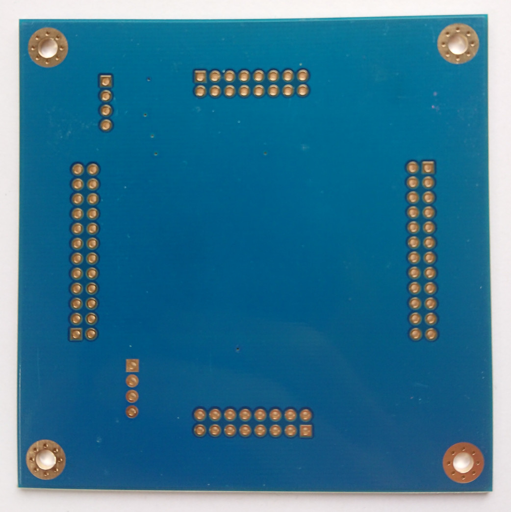
GB-BRK-CPU-G2 v0.1
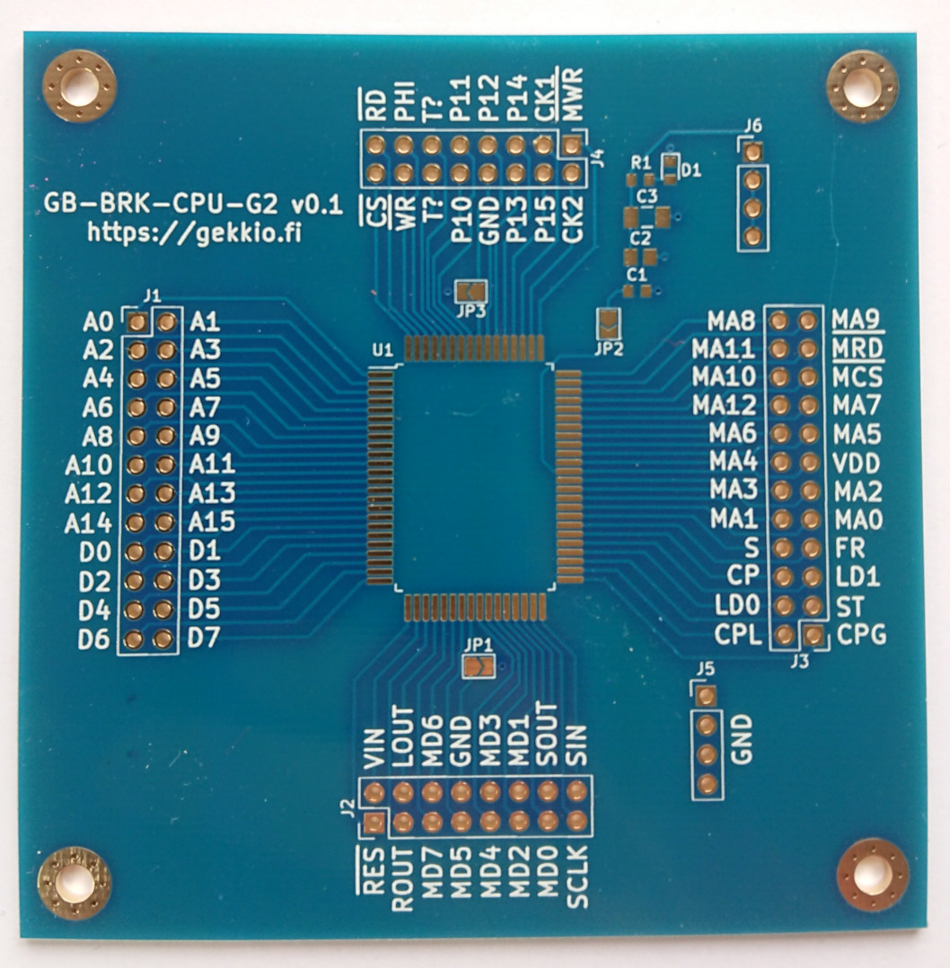
Designed with KiCad, manufactured in 2018 by Elecrow.
This is just like GB-BRK-CPU-G1, but for 2nd generation Game Boy CPUs (Game Boy Pocket, Super Game Boy 2) which use a different pinout. When I made this initial v0.1 design, I wasn't sure about some pins, so the test pins are labeled T?, and there are some other minor differences compared to the later versions.
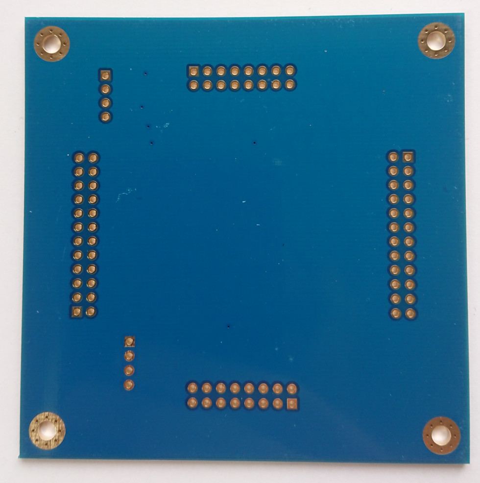
GB-BRK-CPU-G3 v0.1
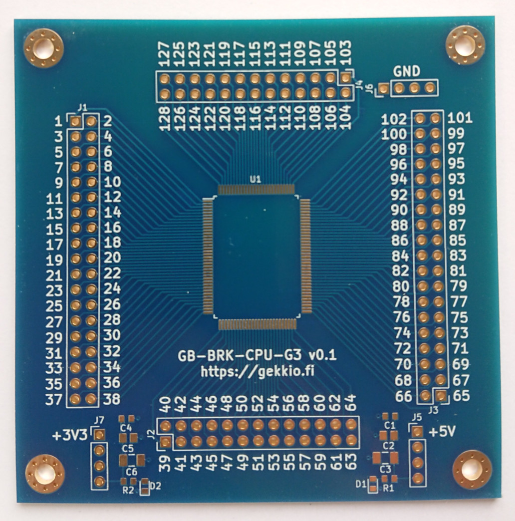
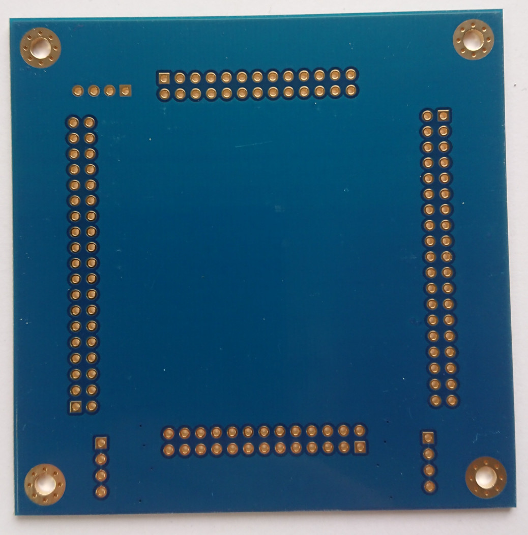
Designed with KiCad, manufactured in 2018 by Elecrow.
This breakout board is for 3rd generation Game Boy CPUs (Game Boy Color). When I made the design, I wasn't sure about the pins at all so I just used numeric labeling.
Useful links
- KiCad PCB design software: https://www.kicad.org/
- Eagle PCB design software: https://www.autodesk.com/products/eagle
- JLCPCB PCB manufacturer: https://jlcpcb.com
- Elecrow PCB manufacturer: https://www.elecrow.com
- My current Game Boy hardware designs: https://github.com/Gekkio/gb-hardware
- My KiCad libraries, including a lot Game Boy -related stuff: https://github.com/Gekkio/gekkio-kicad-libs